ALTERA DE1 USB BLASTER DRIVER DOWNLOAD

| Uploader: | Bamuro |
| Date Added: | 27 June 2009 |
| File Size: | 56.84 Mb |
| Operating Systems: | Windows NT/2000/XP/2003/2003/7/8/10 MacOS 10/X |
| Downloads: | 14448 |
| Price: | Free* [*Free Regsitration Required] |
You need to click the Configure button to enable the connection from the Flash Memory xltera the Asynchronous Port 1 of the Flash Controller indicated in Figure 3.
Terasic - SoC Platform - Cyclone - DE1-SoC Board
Now cancel this probably by selecting Cancel 4. The LEDs will appear to be dimly lit; this is normal.

As indicated in the schematic in Figure 4. A schematic diagram that shows the pushbutton and toggle switches is given in Figure 4. IEE Floating Point addition 7. These switches are not debounced, and are intended for use as level-sensitive data inputs to a circuit.
As shown in Figure 5. DAC input digital signals, how to generate? Select the Asynchronous 1 port for the Flash Multiplexer and then click on the Configure button to activate the port.
The following will appear on the screen: Reset vector and exception vectors need to be assigned. The Sequential Read function is used to read the data stored in the Flash memory and write this data into a file as follows: The data RGB inputs on the monitor must be off driven to 0 V for a time period called the back porch b after the hsync pulse occurs, which is followed by the display interval c.
Connect your headset to the Line-out audio port on the DE1 board 5. Altera products are protected under numerous U.
Altera FPGA DE1开发板简介_图文_百度文库
Your board should light up all of the red, green, and 7-segment LEDs. Sign up using Email and Password.
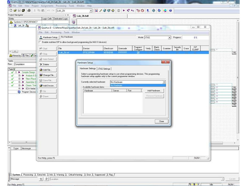
I want that variable to be exported to a program through the USB Blaster. In the Programmer window you should now see the USB blaster selected as a programmer.
All other product or service names are the property of their respective holders.
alterz Read one byte from the memory Write a binary file to the memory Load the contents of the Flash memory into a file Note the following characteristics of the Flash memory: The setup for the SD music player demonstration. Amplifier Yamaha RX-V not turning on hsb Schematic diagram of the expansion headers. Frequently Asked Questions Q. Using this connection, the board will be identified by the host computer as an Altera USB Blaster device. Eagle PCB clearance error 2.
Post as a guest Name. By clicking "Post Your Answer", you acknowledge that you have read our updated terms of serviceprivacy policy and cookie policyand that your continued use of the website is subject to these policies.
Altera USB Blaster Driver Installation Instructions
On my system it is located in: Resample the original image to have a x resolution. Pin assignments for the 7-segment displays. Before you click on it save whatever stuff you need to save since the restart is almost immediate.
A Command Controller circuit interprets the commands received from the PC and performs the appropriate actions. When you turn off the board, the FPGA loses this programming information.


Comments
Post a Comment