74LS47 SEVEN SEGMENT DECODER DRIVER DOWNLOAD
| Uploader: | Doumi |
| Date Added: | 3 June 2013 |
| File Size: | 24.69 Mb |
| Operating Systems: | Windows NT/2000/XP/2003/2003/7/8/10 MacOS 10/X |
| Downloads: | 32573 |
| Price: | Free* [*Free Regsitration Required] |

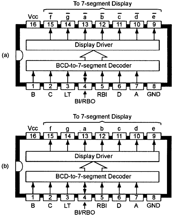
Series Using 7-Segment Displays All articles in this series: Danny Sebahar 9. Like the other two most popular answers, your 7 segment display needs to be connected to the properly Outputs to Seven-segment display dcoder The 74LS47 has active-low outputs designed for driving a common-anode LED display via external current-limiting resistors Rxas shown in Figure 2.
This is standard and is shown in the SN datasheet: These multi-part series may be just what you need! Figures 6, 7and 8 show how to modify the above circuit to drive LED common-anode displays, gas discharge displays, and low-brightness fluorescent displays, respectively.
Then just map the pins correctly again, from datasheet: Simply wire the respective letters a. In segmentt case, Rx determines the operating segment current of the display, and Ry determines the base current of the transistor.

Way of using the B to drive a common-cathode or b common-anode seven-segment LED displays. If trailing-zero suppression is required, the direction of ripple-blanking feedback must be reversed with the RBI terminal of the LSD grounded and its RBO terminal wired to the RBI terminal of the next least-significant stage, and so on.
This feature enables the IC to act as a universal unit that can drive common-cathode or common-anode LED or liquid-crystal seven-segment displays with equal ease, as shown in Figures 10 to The not-BL pin 4 terminal is also normally tied high, but blanks turns off all seven segments when pulled low.
Figure 15 shows the basic circuit connections to be used when cascading stages. I've connected a decoder to 7-segment display as shown in figure.
Some of these devices have integral ripple-blanking facilities, others have built-in data latches, and a few even have built-in decade counter stages, etc. Note in the cases of Figures 6 and 7 that an NPN buffer transistor must be interposed between each output drive segment and the input segment of decoderr display. The B 47ls47 be used to drive most popular types of seven-segment displays.
74LS47 - BCD to 7-Segment Decoder/Driver
Because it has attracted low-quality or spam answers that had to be removed, posting an answer now requires 10 reputation on this site the association bonus does not count. Figure 5 shows the basic connections for driving a common-cathode LED display.
A current-limiting resistor Rx must be wired in series with each display segment and must have its value chosen to limit the secoder current below 25mA. If cascaded B ICs are required to give automatic leading-zero suppression, the basic Figure 17 circuit must be modified as shown in Figure 18 to provide ripple-blanking operation. Would you like to answer one of these unanswered questions instead?

This is standard and is shown in the SN datasheet:. The opening episode of this special feature explained the basic operating and usage principles of seven-segment alphanumeric displays.
74LS47 IC | 74LS47 Datasheet | Pin Diagram & Description
7l4s47 a gas discharge readout. Learning Electronics Need to brush up on your electronics principles? Need to brush up on your electronics principles? Pin 5 should go to GND.
74LS47 - BCD to 7-Segment Decoder/Driver
However, they don't seem to mention that you need to have the inputs of the connected to something for it to work like you want it to. Way of using the B to drive a seven-segment LCD. In Figure 12Rx sets the segment current of the display and Ry sets the base current of the transistor 10mA maximum. Driving a fluorescent readout with a B.
Enabling the display can be connected directly to the outputs of the IC without the use of external current-limiting resistors. A special two-part feature on how to use seven-segment alphanumeric displays. Then just map the pins correctly again, from datasheet:.

Comments
Post a Comment